Visio Plan 2 Visio Plan 1 Visio Professional 2021 Visio Professional 2019 Visio Professional 2016 Visio Professional 2013 Visio Premium 2010 Visio 2010 More...Less
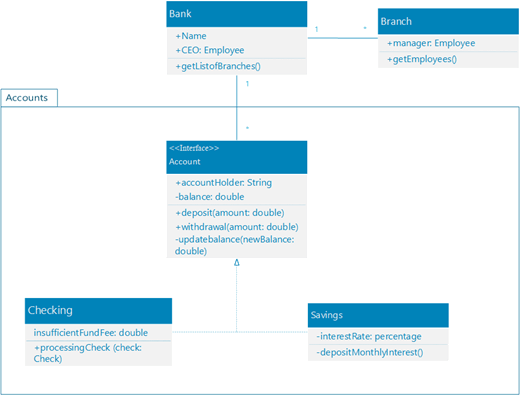
You can create a UML class diagram to show a static view of a system's classes, their attributes and methods, and the relationships among objects. It gives an overview of an application.
(The Professional editions of Visio include support for the UML Class diagram and stencil, but the Standard editions don't.)
When you start a new class diagram, the UML Class stencil appears, along with shapes that conform to the UML 2.5 standard.
-
Start Visio. Or if you have a file open already, click File > New.
-
In the Search box, type UML class.
-
Select the UML Class diagram.
-
In the dialog box, select the blank template or one of the three starter diagrams. (A description of each one is shown on the right when you select it.) Then select either Metric Units or US Units.
-
Select Create.
-
The diagram opens. You should see the Shapes window next to the diagram. If you don't see it, go to View > Task Panes and make sure that Shapes is selected. If you still don't see it, click the Expand the Shapes window button on the left.
-
On the View tab, make sure the check box next to Connection Points is selected. This option makes connection points appear when you start connecting shapes.
-
Now, drag shapes you want to include in your diagram from the Shapes window to the page. To rename text labels, double-click the labels.
-
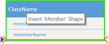
To add more members to the class, enumeration or interface shape, drag the member shape from the shape panel to the respective shape. You can also add a new member by right-clicking an existing member and choosing the option to insert a member.
-
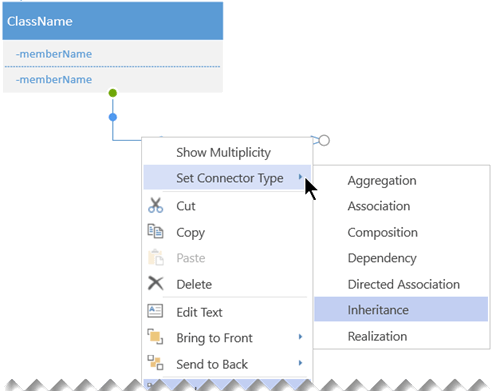
Connect two shapes with UML connectors to represent the relationships between the shapes. To change the relationship types, right-click the connector. Choose the desired relationship from the Set Connector Type menu.
-
Resize a class, enumeration, or interface shape by clicking the shape header to select it and then moving the yellow control point (on the right edge of the shape) left or right to decrease or increase the width of the shape.
-
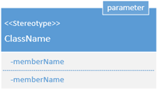
Add parameter and stereotype fields to your class shapes by selecting the shape, right-clicking and choosing the corresponding option from the pop-up menu.
First, you create a diagram and add a UML class stencil that has shapes that conform to the UML 2.5 standard.
-
Open Visio for the web.
-
Near the upper right corner of the page, select More templates.
-
In the Gallery, scroll down to the UML Class row, about midway down the page.
The first item in the row represents a blank template plus the companion stencil. The other items in the row are sample diagrams that have some shapes already drawn to help you get started quickly.
-
Click any item to see a larger preview.
-
When you find the diagram you want to use, click its Create button.
The new diagram, with the related stencil, opens in your browser. You're ready to begin drawing your diagram.
-
Now, drag shapes you want to include in your diagram from the Shapes window to the page. To rename text labels, double-click the labels.
-
To add more members to the class, enumeration or interface shape, drag the member shape from the shape panel to the respective shape. You can also add a new member by right-clicking an existing member and choosing the option to insert a member.
-
Connect two shapes with UML connectors to represent the relationships between the shapes. To change the relationship types, right-click the connector. Choose the desired relationship from the Set Connector Type menu.
-
Resize a class, enumeration, or interface shape by clicking the shape header to select it and then moving the yellow control point (on the right edge of the shape) left or right to decrease or increase the width of the shape.
-
Add parameter and stereotype fields to your class shapes by selecting the shape, right-clicking and choosing the corresponding option from the pop-up menu.
First, you select the UML Class diagram, which comes with a class stencil containing shapes that conform to the UML 2.0 specification.
-
Start Visio. Or if you have a file open already, click File > New.
-
In the Search box, type UML class.
-
Select the UML Class diagram.
-
In the dialog box, select either Metric Units or US Units.
-
Select Create.
-
The diagram opens. You should see UML Class stencil in the Shapes window next to the diagram. If you don't see it, go to View > Task Panes and make sure that Shapes is selected. If you still don't see it, select the chevron on the left margin of the window Expand the Shapes window button.
-
On the View tab, make sure the check box next to Connection Points is selected. This option makes connection points appear when you start connecting shapes.
-
Now, drag shapes you want to include in your diagram from the Shapes window to the page. To rename text labels, double-click the labels.
In Visio 2010, the way to create a UML class diagram is by using a Static Structure diagram. See Create a UML static structure diagram for details.
Tips for creating a class diagram
-
Identify each element and its relationships.
-
Clearly identify what each class is responsible for.
-
Don't include unnecessary properties in the diagram that might make it too complicated.
Class notation
| Symbol | Meaning |
|---|---|
| - | The attribute or operation is private. |
| + | The attribute or operation is public. |
See Also
UML diagrams in Visio
Need more help?
Source: https://support.microsoft.com/en-us/office/create-a-uml-class-diagram-de6be927-8a7b-4a79-ae63-90da8f1a8a6b
Posted by: sankobennyoes.blogspot.com

Posting Komentar